Shear strength measurement is the primary method used to evaluate how well friction material bonds to the backing plate. Standards like ISO 6312 and SAE J840B set clear benchmarks — requiring at least 80% material retention on the bonded surface. These automotive safety standards define specific force ranges, typically between 3–5 N/mm² in the axial direction, along with radial forces applied perpendicular to the pad surface.
This guide walks you through the standards, equipment, and material factors that define a proper brake pad shear test. Because shear performance is ultimately determined by the composition and interaction of friction materials, binders, and reinforcements, understanding the underlying material design is essential. For a deeper explanation of how these elements influence bonding strength, thermal stability, and overall braking performance, explore our brake pad technology guide. Whether you design brake systems or manufacture friction components, you need to understand how these tests ensure your products can handle the intense stresses of real-world braking events.
Understanding the Brake Pad Shear Test Standards and Requirements
When you evaluate brake pad safety, you need a clear understanding of the standards that govern shear testing. Several international testing protocols define how engineers measure bond strength between the friction material and the backplate. Each standard outlines specific parameters — ram offsets, speed rates, and temperature conditions — that ensure consistent and repeatable results across labs worldwide.
ISO 6312 and SAE J840 Testing Parameters
The ISO 6312:2001 standard defines test conditions for evaluating the shear strength of brake linings, including controlled displacement rates and, in some cases, elevated temperature testing to simulate high thermal stress during braking.
Engineering studies and industry references indicate that ISO-based testing may involve displacement-controlled loading (e.g., around 10 mm/min) and elevated temperature conditions reaching up to 300°C, depending on the specific test setup and application requirements.
SAE J840B:1998 applies a similar testing principle but typically uses tighter displacement ranges and comparatively lower thermal conditions, reflecting differences in testing focus within North American standards.
Japanese Industrial Standards (JIS) follow comparable mechanical testing methodologies, often emphasizing baseline bonding performance under controlled conditions, with some protocols focusing primarily on room-temperature evaluation.
These variations across ISO, SAE, and JIS frameworks demonstrate how different regions prioritize specific aspects of brake pad performance, particularly in relation to thermal behavior, bonding strength, and durability.
Critical Force Application Methods: Axial and Radial Loading
During shear strength testing, engineers apply force in two primary directions to evaluate the bonding integrity between the friction material and the backplate.
Axial loading refers to force applied parallel to the pad surface, generating shear stress that pushes the friction material sideways off the backing plate. This simulates tangential forces experienced during braking.
Radial loading applies force perpendicular to the bonding interface, helping assess resistance to peeling or delamination under structural and thermal stress.
According to ISO 6312 shear testing methodology (see ISO 6312 shear test standard), bonding strength is evaluated under controlled loading conditions until failure occurs, providing a standardized approach to assessing adhesion performance.
Experimental observations, including studies such as those by Saikrishnan et al., show that shear tests may involve applying side loads to the brake pad surface while introducing vertical force until complete bond failure occurs. This combined loading method reflects the interaction of shear and compressive forces in real braking environments.
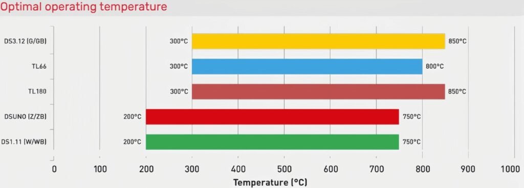
Temperature Conditions: Room Temperature vs Hot Testing at 300°CISO 6312 reference
Temperature plays a critical role in evaluating brake pad shear strength and bonding durability. Room temperature testing provides a baseline for adhesive performance under standard conditions, while elevated temperature testing—typically at 205°C or up to 300°C—reveals how thermal exposure affects bond integrity and failure behavior.
According to the International Organization for Standardization standard ISO 6312:2010, shear testing is specifically designed to measure the strength of the bond between the friction material and the backing plate under controlled loading conditions.
While ISO 6312 primarily defines the methodology and loading conditions, complementary standards such as ISO 6313 highlight the importance of temperature in brake lining performance, including dimensional stability and heat resistance.
In practice, high-temperature shear testing simulates real braking scenarios where friction-induced heat can significantly weaken adhesive layers. At temperatures approaching 300°C, degradation mechanisms such as resin softening, oxidation, and thermal expansion mismatch become critical, often leading to reduced shear strength or premature bond failure.
By comparing room temperature and elevated temperature results, engineers can better assess whether a brake pad maintains structural integrity under extreme operating conditions—ensuring reliability before advancing to full dynamometer or vehicle-level testing.
Essential Testing Equipment and Methodology
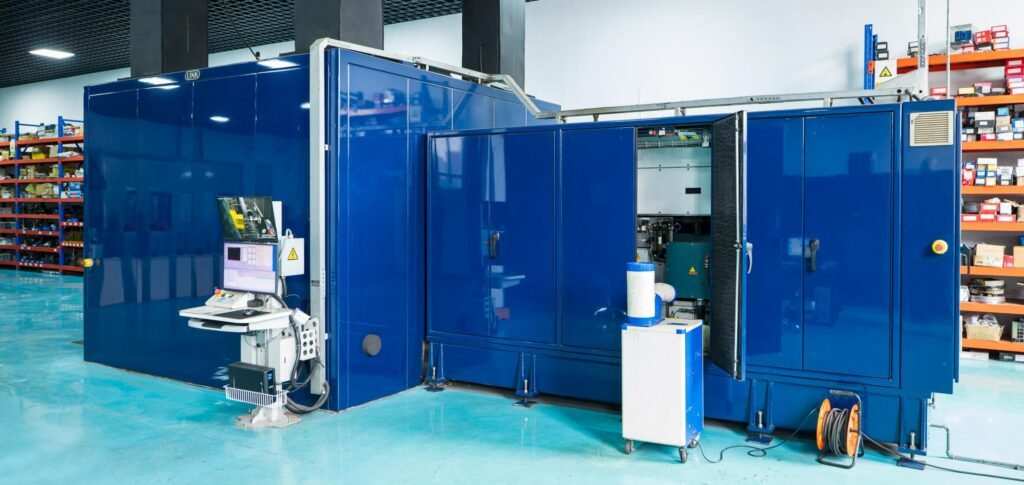
Getting accurate shear test results starts with the right tools. You need reliable brake pad testing machinery that delivers repeatable force application under controlled conditions. From hydraulic presses to specialized rigs and tribometers, each piece of equipment plays a distinct role in the testing workflow.
Hydraulic Press Systems and Specialized Shear Test Rigs
During hot compaction, hydraulic testing equipment operates at pressures around 20 MPa. Upper molds reach 168°C while lower molds hit 177°C — and the cycle runs for about six minutes. These compression molding systems create the bond between friction material and the steel backplate.
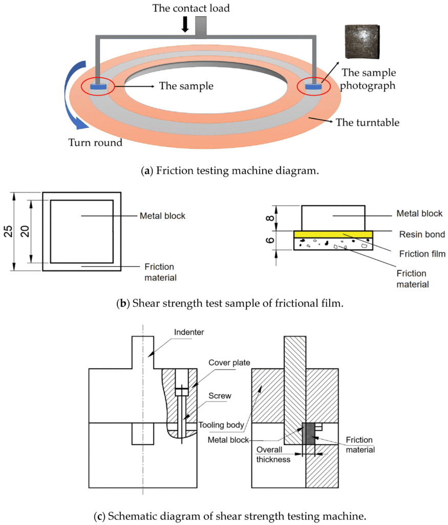
Once pads are molded, a dedicated shear test apparatus holds the sample in place. The rig applies a graduated load directly to the friction material until the bond fails. Post-treatment at 170°C for two hours strengthens the thermoset matrix before testing begins.
Ram Offset Specifications and Constant Speed Rate Applications
Precision matters when you configure the ram. Key parameters include:
- Ram offset ranging from 0.25 mm to 1.0 mm, depending on the applicable standard
- A constant crosshead speed of 10 mm/min for uniform load application
- Proper alignment to prevent eccentric loading during the test
These specifications — drawn from ISO 6312 and SAE J840B — ensure that every test run produces comparable data across different labs and brake pad testing machinery setups.
Measurement Techniques for Backplate Adhesion Strength
Beyond shear force, adhesion strength measurement tools capture a broader performance picture. Pin-on-disc tribometers spin at 200–1,000 rpm under loads of 10–30 N. You can expect friction coefficients between 0.63 and 0.795, with wear rates from 0.85 to 1.065 mg/N.
These metrics give you a complete view of how well a pad formulation resists both shear and wear — critical data we’ll explore in the material analysis that follows.
Performance Evaluation Through Material Analysis
After shear testing, you need to understand what happened inside the brake pad at a microscopic level. This is where surface characterization techniques come into play. These methods let you see the exact failure modes and material changes that occur during testing.
SEM imaging brake pads is one of the most powerful tools in your evaluation toolkit. Scanning Electron Microscopy — especially in back-scattered electron mode — reveals dust distribution, erosion patterns, and crack propagation across the friction surface. Since brake pad composites are non-conductive, samples require a thin gold coating before examination.
EDAX elemental analysis works alongside SEM to map the exact chemical composition across the sample. Energy-dispersive X-ray spectroscopy identifies elemental quantities and their distribution within the composite matrix. This data is essential for understanding how different ingredients behave under stress.
A thorough microstructural analysis typically includes these key observations:
- Fiber pull-out patterns indicating adhesion failure between reinforcements and the resin matrix
- Particle fragmentation caused by excessive shear forces at the backplate interface
- Localized matrix softening in regions exposed to elevated temperatures
- Cutting abrasion on fibers and fatigue cracking in the matrix at temperatures around 150°C
- Fiber decomposition and severe degradation at temperatures exceeding 250°C
Wear mechanism evaluation benefits from advanced tools like Field Emission SEM and Laser Scanning Confocal Microscopy. These instruments provide three-dimensional surface profiles that standard SEM cannot capture. Hardness testing per ASTM D785 on the Rockwell C scale rounds out the assessment — particularly for composites containing hard ceramic fillers.
By combining these analytical methods, you gain a complete picture of how your brake pad composition performs and where it fails under real-world conditions.
Comparative Assessment of Brake Pad Compositions
When you compare different brake pad formulations, the composition tells the whole story. Each ingredient plays a specific role in shear resistance, thermal stability, and overall safety. Let’s break down how these compositions stack up against each other.
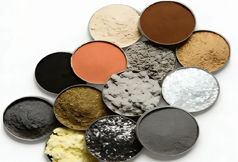
Non-Asbestos Organic Materials vs Traditional Formulations
NAO brake pad materials have replaced older asbestos-based designs across the industry. A typical non-asbestos organic mix uses about 11% Novolac-type phenolic resin (PF-234) with a softening point between 98–105°C. This provides the structural cohesion you need for reliable shear performance. Natural fibers — like date palm fibers with 62% cellulose content and a density of 1.35 g/cm³ — serve as eco-friendly reinforcements in these modern blends.
Impact of Fiber Reinforcements on Shear Resistance
Aramid fiber reinforcement at roughly 7% concentration dramatically boosts mechanical strength and wear resistance. These fibers create an interlocking network within the pad matrix. This network resists cracking and delamination during high-stress braking events — exactly the properties that shear testing evaluates.
Role of Phenolic Resins and Binders in Structural Integrity
Phenolic resin binders require curing temperatures between 170–180°C. They function as high-temperature adhesives that ensure strong interparticle bonding. Without proper resin distribution, the friction material separates from the backplate under load. Barite — used at concentrations around 26.5% — adjusts density and dimensional stability alongside these binders.
Influence of Metallic Additives and Ceramic Components
Metallic friction modifiers like steel wire (approximately 5%) improve thermal diffusivity and load-bearing capacity. Ceramic brake pad components round out the formulation:
- Zirconium oxide (4%) — melting point of 2,715°C — stabilizes friction coefficients
- Magnesium oxide (7%) — melting point of 2,852°C — delivers thermal stability
- Silicon carbide (3%) — enhances wear resistance under extreme conditions
Understanding how these elements interact gives you a clear picture of why certain compositions outperform others in shear testing.
Conclusion
Brake pad shear testing plays a vital role in brake pad safety validation — ensuring friction materials stay bonded to backing plates under extreme stress. Standards like ISO 6312, SAE J840B, and JIS
4422 set clear benchmarks, requiring at least 80% material retention across temperatures from ambient conditions up to 300°C. The shear test importance cannot be overstated, as it directly reflects how a brake pad will perform during real-world braking events.
Quality assurance testing through tools like SEM imaging, EDAX analysis, and hardness measurements gives engineers a detailed look at material behavior. Non-asbestos organic formulations — when paired with optimized phenolic resin content, strong fiber reinforcements, and ceramic additives — consistently outperform older compositions in shear resistance. These insights guide smarter material choices and drive manufacturing compliance standards across the industry. For a comprehensive breakdown of material composition, friction behavior, and engineering design, explore our brake pad material design.